A simple and efficient circuit to program the popular microcontroller with the Arduino IDE (and another to test it with a Raspberry Pi)
As much as things are small and powerful, as much they are difficult to manage. But I never resign! The thing that really lost me a lot of time in this project is the number of unverified instructions and suggestions I found on the Internet.

If I had difficulty finding the right approach and selecting those having sense I can’t imagine a newbie that decided to approach the microcontroller world for the first time with the ESP8266.
Showing a decently verified circuit and eventually also testing it is at least a question of respect to the Makers’ community.
As part of the project for the Super Smart Home on Element14, the goal is to set up an ESP8266-01 small board to activate a relay (both provided by Digitspace).
I have developed a small prototype programmer (it can be done more and more better) that works, accordingly to the specifications of the ESP8266-01 datasheet when it is set in programming mode.
Thanks to the USB to serial adapter from the Cypress PSoC 4 board it was possible to ignore the problem of the signal levels compatibility so only the USB 5V power line has been reduced with an LM1085, the last I have found here around.

The first tests have been done using the bench power supply programming the ESP with the Arduino IDE on a laptop but I needed a more flexible method to follow the development lifecycle of the ESP.

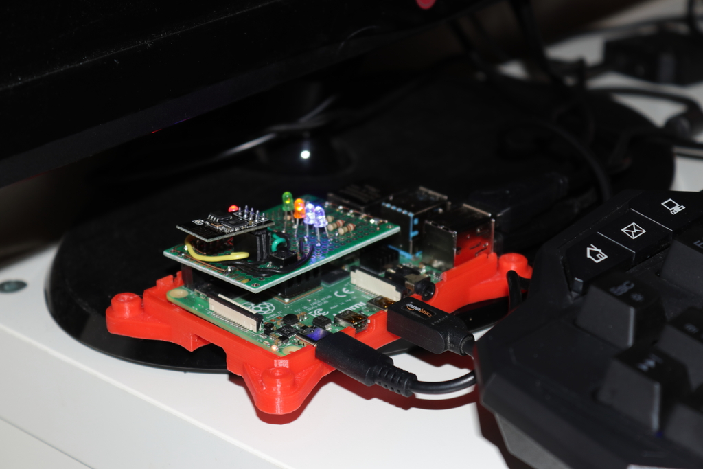
To create an ESP8266 tester I have decided to use a Raspberry Pi configured as desktop; on this SBC both signals and power voltage work at 3V3 so I made a prototype Pi Shield for efficiently test the board, including the serial communication. Changing a while the programmer circuit I made the scheme shown below

To avoid damaging the Raspberry Pi testing the ESP8266-01 the plug/unplug procedure is the follwing:
To Remove the ESP8266
- Power off the switch on the shield
- Optionally disable the Serial Pi Tx signal (suggested)
- Remove the ESP8266
To Insert the ESP8266
- Shutdown the Raspberry Pi
- Insert the ESP8266 board
- Power on the board and also the Raspberry Pi will power on.

This project has been created thanks to the components sponsored by Digitspace. Follow the Super Smart Home challenge on the Element14 Community for more details on this project and more.