Abstract from the book Progetti per maker con Raspberry Pi, Ed. Hoepli, Milan (Italy)
Translation, M.A. Ricagno
Foreword
This project will cover the realization of a Cluster using four Raspberry Pi’s 4B. Personally, I’ve always been very interested in the realization of supercomputers built with more than one processor; in the last two years the experiments for the creation of this kind of systems – i.e. Cluster Computers – have multiplied thanks to the possibilities offered by the Raspberry Pi models. The first Cluster projects based on this platform were published shortly after the release of the second generation of Raspberry; given the rather limited computing power of the Pi 2 model, these were almost always academic experiments aimed at demonstrating how a group of small networked computers can considerably increase the computing power to perform repetitive or time-consuming tasks, especially when performed on single-board computers such as the Raspberry Pi 4B.
Computer Cluster
The English term Cluster literally means “collection”, but also “group”. This word is used in very different fields, such as mathematics and statistics, where Cluster Analysis takes into account the behaviour of certain groups of entities in relation to each other. In the computer field, a Computer Cluster consists of a group of independent computers connected to each other through a network and controlled by a main server. These machines are identical or structurally very similar; each computer in the cluster – identified as a node – has its own operating system installation; the nodes in the cluster communicate quickly and efficiently with each other connected by a local network. In many ways, although they are different machines, the cluster can be seen as a single entity. Each node is configured so that it can perform the same tasks as the other nodes, while the main node (the cluster server) has a software able to establish the priority of execution of each task by distributing the pending tasks to the various nodes according to the availability of resources.
The Cluster Architecture
In this project I used four Raspberry Pi 4B to create a cluster of four nodes: the number of nodes depends on how many units we have available and the system is completely modular, able to be extended to an indefinite number of nodes; some universities have created clusters with hundreds of Raspberry Pi connected to the network. Of course, this also applies in the opposite direction: nothing prevents us from creating a cluster with only two or three nodes. It is obvious that the number of nodes can significantly affect the system performance, seen from the outside as a single entity, a small supercomputer. Despite the flexibility and modularity of the cluster, when it comes to designing the architecture there are some aspects you have to take into account.
Connecting the Nodes
A cluster, based on Raspberry Pi works efficiently using the Pi3 models and the recent Pi 4B. Even though there are no technical problems, if you want to use previous models, these are significantly slower, so the results obtained have more of a demonstrative value of the incredible potential of this small computer.
The Raspberry Pi 4 is the first in the series to offer a 1 Gb Ethernet port and this is one of the most important reasons to prefer this platform model. In order for the nodes to work synchronized with each other, we will use the network; the faster the connection, the faster the system will be. For the same reason, it will be necessary to use a dedicated hub-switch (there are many low-cost models available on Amazon) able to support the maximum speed of the connected nodes. If we are near the internet router, an additional free port must be available on the Hub to connect it to the internet router. Alternatively, the internet connection to the nodes can be made using the WiFi port. As for the speed of the network, the aspect that interests us most is the connection between the nodes, regardless of the internet bandwidth we have: the communication between the nodes does not involve the access to the external network.
Mass Storage
Having a cluster of some Raspberry Pi’s is useful if it can be used in repetitive applications requiring a lot of time and resources, such as complex compilations or recursive editing (e.g. automatic resizing of large amounts of images). Our architecture will, therefore, require also a device on which to store the material. A 2.5-inch hard drive or – better yet – an SSD (possibly recovered from an old laptop) can work very well. In this case too, with the Raspberry Pi 4B, we will have a considerable advantage: the external mass storage can be connected via a SATA-USB converter. By connecting the adapter to one of the two USB 3 ports available on the Raspberry Pi 4B, the data transfer speed will be almost identical to the standard SATA II connection.
The SATA Interface
Currently, the SATA interface is one of the most widely used for connecting mass storage units to computers. SATA is the acronym for Serial AT Attach; it is a fast serial communication bus, originally used on AT computers, which has almost completely replaced parallel buses to connect hard drives, optical devices, and storage media in general to computers.
The choice to use an external medium is not only due to the possibility of having considerable storage space available, but also to reduce as much as possible the read and write tasks of the microSD card on which the operating system resides. If the use of the cluster does not require the management of a large amount of information, alternatively we can replace the hard disk with a USB memory, which will probably be much slower.
The Operating System Version
As I decided to create the cluster with four Raspberry Pi’s 4B, I used the latest Raspbian release, Buster. Regardless of the card and operating system model you adopt, it is still a good rule that the nodes are identical with the same operating system version. This choice greatly simplifies both the initial configuration and the future updates and ensures maximum performance, avoiding both hardware and software incompatibility.
The Cluster Container
In most cases, the realization of the container and the most aesthetic parts of the project is almost always the last task, after verifying that a first version of the prototype is able to work. In this case, I followed the opposite path, because having the four Raspberry Pi’s 4B installed in a functional structure contributes greatly to the stability of the system. The bulk of the cluster implementation work is related to the software configuration, the network, and the operating system.
Before proceeding, the four Raspberry Pi must be assembled and connected to each other, including a cooling system, which is essential, especially if it is based on the Pi 4B.
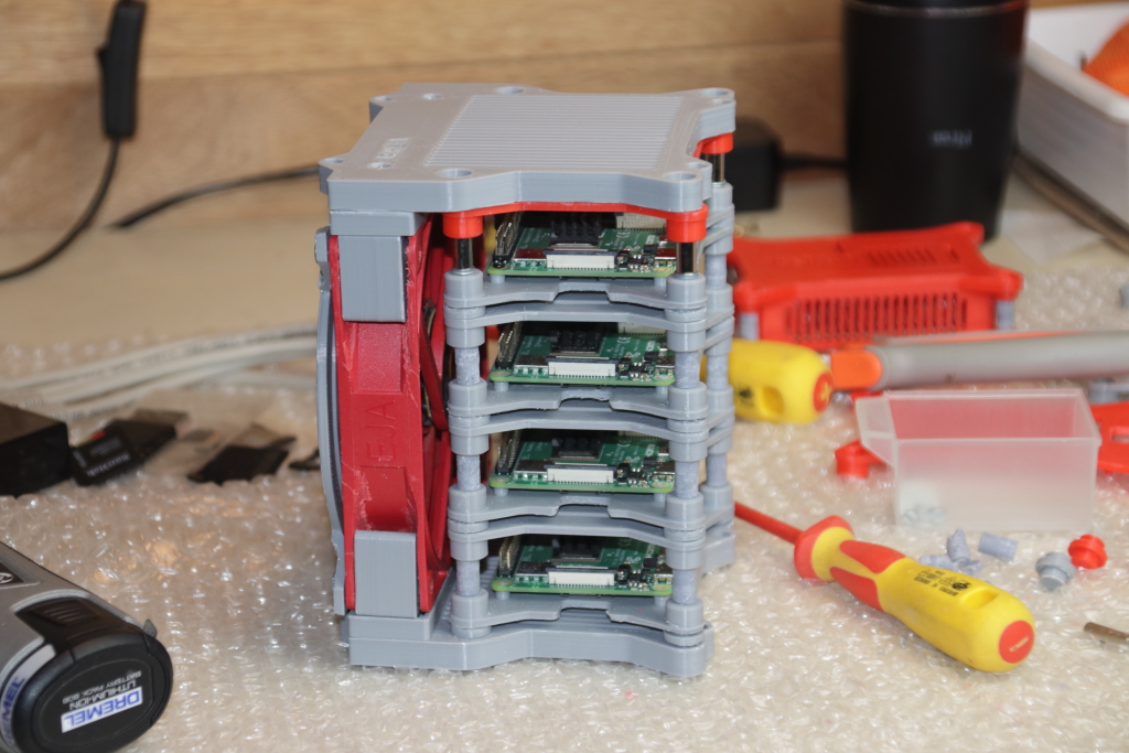
On the thingiverse.com platform, you can find a lot of container drawings to be printed in 3D to make clusters with four or more Raspberry Pi’s; the solution I adopted is the modular structure made by Andrew Overly, easy to print and very well documented. By downloading the entire package of components and STL files ready for 3D printing, you can configure different solutions that include separate cases for each card with room for fixing the cooling fan or modules able of accommodating four Raspberry Pi.
As I had a fan recovered from an ATX power supply with a 22-centimeters diameter, I printed the necessary files to assemble a module of four Raspberry Pi with a single side cooling fan. Andrew Overly’s original design also includes the mains Hub-switch housing and a four-position USB power supply; I have excluded these two additional components using four separate power supplies, one for each card, a fifth 12 V power supply for the cooling fan and one for the Hub.
The network is also connected externally with about 20 cm long patch RJ45 cables. After assembling the structure, the cluster is ready to be configured and made operational.
The Nodes Configuration
The cluster is identified on the network via the main node; this has two important features that differentiate it from the other nodes: it includes mass memory – in this case, I used a 2.5-inch terabyte hard drive – and the cluster management software that works as a server. On the other nodes, instead, the software corresponding to the clients will be installed.
The Role of the Main Node
As we said, once configured the cluster is seen on the network as a single machine; as a matter of fact, all the cluster functionalities, when it is operational on the network, pass through the main (or master) node, which takes care of distributing the tasks to the secondary nodes. In the same way, the computers that will use the cluster resources will have the master’s mass memory as a data exchange and storage area. The main node will not only act as a master to the outside but after a first configuration of the cluster nodes, all the installed programs will use the main node as a distribution point.
When designing the architecture of a cluster based on Raspberry Pi, it is important not to forget that the master node does not take care of the processes but only of the correct distribution and synchronization of the exchange of data and processes on the remaining three client nodes.
Keeping the Nodes Synchronized
Although installing a certain program on only one or a few nodes is technically possible, this is not a recommended practice. The most correct approach, especially for efficient cluster maintenance, is to have always all the machines synchronized with the same programs updated to the same version, as well as the operating system.
An exception to this procedure is the installation of utilities on the master node (which does not contribute to process sharing).
Preparation of the MicroSD Card
In order to work in the best possible conditions, all the Raspberry Pi’s used for the nodes are identical machines. Simply download the Headless version (without desktop) of the Raspbian distribution you intend to use and create as many microSD cards as are the nodes.
Network Settings
When the Raspberry Pi is started for the first time connected to the internet router via the Ethernet cable, it uses the DHCP (Domain Host Control Protocol) service of the router which assigns the machine the first free IP address on the local network among a group of IP’s reserved for DHCP (this depends on the configuration of the router). In our case, however, we need to assign a static IP address to each node so that it can always be identified on the network in the same way. The first thing to do is to disable the router’s DHCP on each node.
In recent versions of Raspbian the network configuration parameters are contained in the file
/etc/dhcpcd.conf
To set up the Ethernet connection of the Raspberry Pi with a static IP, you need to edit this file by adding the static IP address configuration block to the bottom of the file.
# Static IP configuration:
interface eth0
static ip_address=192.168.1.128
netmask 255.255.255.0
To assign a static IP you need to be familiar with a minimum of the router configuration; this information can be easily found by accessing the router IP address (Adsl or fiber) through the browser which usually corresponds to a local web page from which you can check the configuration and set some parameters. As an example, consider the local network configuration with the following parameters:
- IP router address: 192.168.1.1
- Network mask: 255.255.255.0
- First DHCP address: 192.168.1.9
- Addresses used by the DHCP: 100
The DHCP server – part of the software of all the internet routers – automatically assigns the first free IP address of the DHCP address pool each time a device connects to the network; the maximum number of devices that can be connected at the same time is defined by the number of addresses reserved for the DHCP server contained in the router. In our example, of all 256 IP addresses available on the 192.168.1.* network, the addresses reserved by the DHCP server will be between 192.168.9. and 192.168.1.108.
Although the use of DHCP group IP addresses as static addresses is not prohibited, when possible it is better to use an IP address that is not part of the pool. In the case described in the example, I used the IP addresses from 192.168.1.128 to 192.168.1.131 to assign them to the four nodes of the cluster.
Assigning a Name to the Nodes
In order to name a Raspberry Pi to identify it – or, more generally, a Linux computer connected on the local network – you need to edit the file
/etc/hostname
by entering a line of text with the name to be assigned to the computer (without spaces or special characters).
In the case of the hostnames to be attributed to the nodes of the cluster, you need to pay extra attention; the software that manages the cluster – installed on all nodes – imposes for each node a name consisting of a prefix followed by a “predictable” number, i.e. a sequential numbering, not necessarily continuous. In order to simplify things, I used the prefix “cluster” and the numbering from 01 to 04. So, the four nodes will have respectively the following hostnames:
- cluster 01 (master node)
- cluster 02 – cluster 04 (client nodes)
Moreover, each node must be recognized by the other three nodes that are part of the cluster through its hostname. In a complex network, you could use a local DNS (Domain Name Server) that associates each static IP address with a corresponding hostname in URL (Universal Resource Locator) format. In the simplest cases with a small number of nodes, however, there is an equally efficient method, which can also be applied to other Linux machines, not just to the cluster architectures.
As a matter of fact, the /etc/hosts file can be used to associate IP addresses to the relative hostnames of the machines that must be recognized with the symbolic name instead of just the numerical address. In practice, the /etc/hosts file works in the local network in a similar manner to the Internet DNS that allows us to access a website through the URL. In fact, in this way, it is called a Static DNS.
Based on the convention of the nomenclature chosen for this cluster, the file content for each node should be:
Note how for each node the name of the node is associated with the IP address 127.0.1.1 which by definition corresponds to the address that the network card assigns to itself.
Accurate Time Management
Much of the efficiency of the cluster depends on the speed of the nodes and the network to which they are connected, but an accurate and synchronized time management is another key element to ensure the system efficiency; in fact, it is necessary that the processes performed by the computers in the cluster are synchronized as accurately as possible.
The NTP Protocol
The next step in the node configuration is the installation of the NTP protocol with the command
$> sudo apt-get install ntpdate
NTP stands for Network Time Protocol and is used to synchronize the processor clock of a group of networked computers. The command ntpdate keeps the Linux computers connected to the same network accurately synchronized.
The same steps for node configuration must be performed on all the machines that are part of the cluster.
Hard Disk Preparation
In this project, I used a 1 Tb, 2.5 inch SATA hard disk connected to the USB 3 port of the master node.
Creating an ext4 Partition
At this point, the disk must be configured as a shared archive accessible by all the nodes. Since you also decided to use the disk as storage space for data from other computers connected to the network, the disk should also be easily accessible as a network visible data archive. To build a shared space between the nodes in the cluster, you need to create an ext4 Linux partition on the disk and configure the nodes appropriately.
To share the disk on the network also with other devices that are not part of the cluster, it is recommended to install the SAMBA protocol on the master node.
For simplicity, I assigned the name “clusterfs” to the shared hard disk that will be accessible as a network resource through the SAMBA protocol. After creating the ext3 partition, you should install the disk with the mount command in the folder representing the symbolic disk link.
$>sudo mkdir /clusterfs
$>sudo chown pi /clusterfs
$>sudo chmod -R 777 /clusterfs
To make the disk mount permanent when you start the Raspberry, you need to edit the /etc/fstab file. To make the disk accessible from all the nodes in the cluster, you need to export the shared folder, which in our case represents the entire disk space, as an NFS share.
Since the main node is the Raspberry that exports the share, we will have to install the NFS server with the command
$>sudo apt install nfs-kernel-server -y
as in the case of all the shared system components on the network, the /clusterfs should be exported by editing the /etc/exports adding the following line:
/clusterfs <ip addr>(rw,sync,no_root_squash,no_subtree_check)
The parameters in brackets in the command indicate how you want to export the disk content, while <ip addr> should be replaced by the IP address assigned to the computer:
rw – Allows the other nodes to access with read and write permissions
sync – It forces the writing of the changes to files and folders immediately
no_root_squash – It enables the root users (supervisor access to the computer) to write and read files with root permissions not accessible by normal users
no_subtree_check – It prevents errors due to writing data to files that are already in use by other computers.
As a matter of fact, the nodes in the cluster must be able to access the same information simultaneously. After saving the changes, you need to update the NFS server with the new configuration using the command
$>sudo exports -a
6.6.2 – Installing the NFS Share
At this point, we need to make sure that the other nodes can mount the NFS share at boot time as if it were a local hard drive. First of all, you should install the NFS protocol client with the command
$>sudo apt install nfs-common -y
So, similarly to the master node, we have to create the folder that virtually represents the disc in the other three nodes:
$>sudo mkdir /clusterfs
$>sudo chown pi.pi /clusterfs
$>sudo chmod -R 777 /clusterfs
Finally, we will update the file /etc/fstab to make the mount permanent every time we start the system on all the client nodes by adding the following line:
<Master Node IP Address>:/clusterfs /clusterfs nfs defaults 0 0
At this point, the basic structure of our cluster is complete and correctly configured.
After a last restart at all nodes, we just have to begin experimenting the computing power of this little supercomputer.
2 replies on “PiCluster How-to”
I am very interested in knowing the exact programming needed for this cluster, can I use the Raspberry Pi 3B+ as I have 4 of them set up as a cluster, I was trying to load Kubernetes but it didn’t work out all that well.
Hello Tim,
the whole software I have used to setup the PiCluster with the experiments I have made is described in the other blog post here: https://we-are-borg.com/wp-admin/post.php?post=329&action=edit
while the same sources are included in the GitHub repository https://we-are-borg.com/wp-admin/post.php?post=329&action=edit
The settings for the cluster characteristics (nodes, configuration etc. are described in this post.
I am preparing a this post on PiCluster where I describe the topology and the components. A full description of the entire project will be available in the book “Progetti per maker con il Raspberry Pi” that will be on sale next month.
In the experiments I have used four Raspberry Pi 4B as this project is part of the road test I wrote for Element14 community (the link is here: https://www.element14.com/community/roadTestReviews/3323/l/roadtest-the-raspberry-pi-4-model-b-2gb-review ) but the Raspberry Pi 3B+ is more than sufficient for many kind of applications.
If you experience further problems or have doubts don’t hesitate to commend and I will answer you as soon as possible.
Enrico